3D modeling of metal parts turns a concept, a sketch or a partial drawing into an accurate digital model and then into a buildable shop drawing. It validates feasibility, optimizes each part for fabrication and confirms dimensions before a single piece of metal is cut.
Many industrial projects start as a sketch on the corner of a table rather than a complete drawing. Getting from that spark to a real part takes genuine 3D modeling of metal parts, a discipline that connects the designer's intent to the reality of the shop floor. That is where lead times, costs and final quality are decided.
A client often arrives with a photo, a part to copy or a written idea. The engineering office's job is to fill in everything that is missing: dimensions, tolerances, alloy selection and assembly method. This article walks through each step, from reading the drawing to the deliverables exchanged by both sides.
Why 3D modeling of metal parts changes everything
Designing in three dimensions is not an aesthetic luxury. An exact digital model becomes the shared reference for the client, the designer and the welder. Everyone works from the same geometry, which eliminates conflicting interpretations.
A well-built model also makes it possible to simulate assemblies, detect interferences and check clearances before any steel is cut. Designing metal parts in SolidWorks also provides exploded views and bills of materials that speed up approval.
This rigor directly meets what industrial buyers look for: traceability, repeatability and documentation. A documented project can be reproduced identically five years later, which reassures the food, pharmaceutical and water treatment sectors.
From idea to digital model: reading and redrawing a plan
The first step is to gather the existing information, whatever form it takes. A good engineering office accepts a freehand sketch, a photo, a partial file or a complete drawing, then rebuilds what is missing.
This redrawing includes several essential checks:
- Consistency of dimensions and tolerances between views
- Alloy and thickness selection based on the intended use
- Welding, bending and assembly constraints
- Applicable standards for the target sector
Material selection happens early because it affects everything else. Understanding, for example, the difference between 304L and 316L avoids oversizing a project or weakening a part in a corrosive environment. This 3D design of custom stainless steel parts always starts from a clear intent.
Validating feasibility before launching production
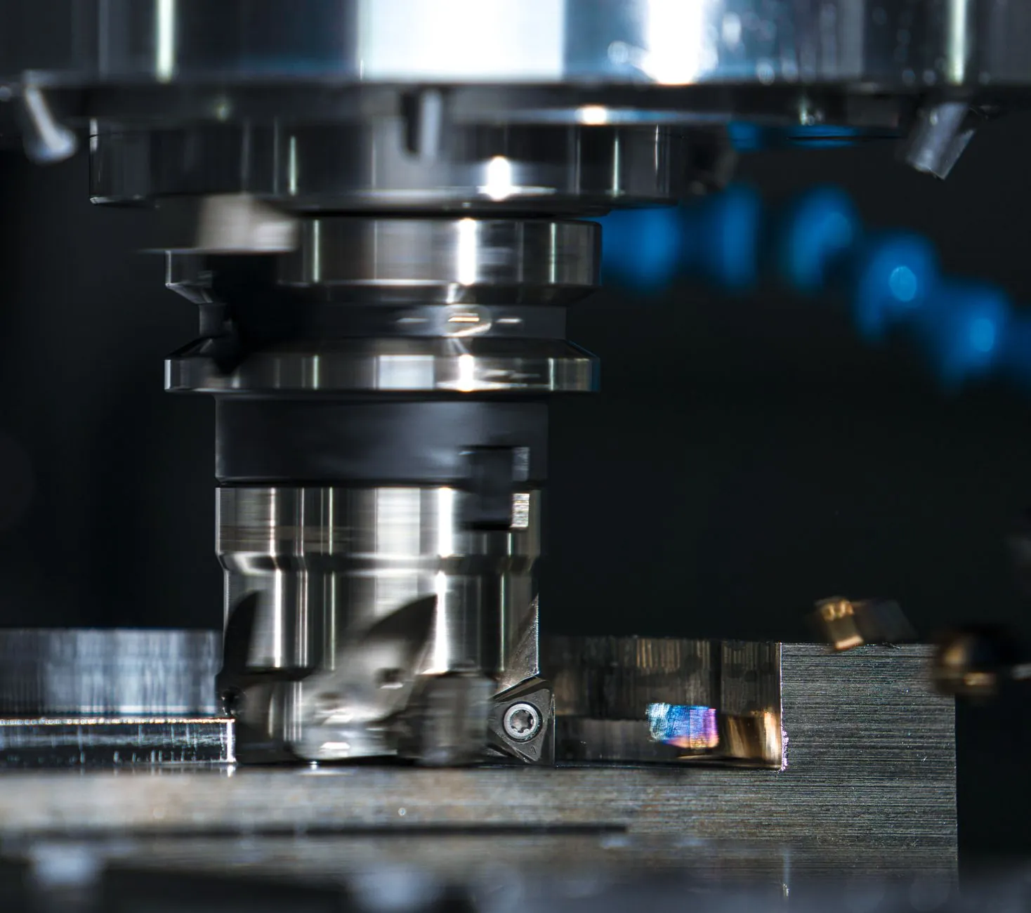
A good-looking drawing is not necessarily buildable. Feasibility validation tests the model against real capabilities: minimum bend radii, tool clearances, weld access and maximum sheet dimensions.
This step relies on proven design rules. Design for manufacturability guidelines cover bend radius, hole-to-bend distance and flange length, among other things. Ignoring these rules leads to cracks, distortion or costly rework.
Working with planners located next to the shop floor speeds up this validation considerably. The question "can the press brake make this bend?" is settled with a twenty-foot walk rather than three days of waiting for an email.
Before committing material and production hours, have your concept tested against the shop's real constraints. Early feasibility validation avoids unpleasant surprises and protects your schedule.
Optimizing each part for manufacturability
Once feasibility is confirmed, optimization begins. The goal is simple: achieve the same function with fewer steps, less material and less risk of error.
The most common optimization levers:
- Reduce the number of distinct parts and welds
- Standardize thicknesses and bend radii
- Nest cuts together to limit sheet scrap
- Tighten tolerances only where they are critical
Tightening a tolerance on a mating surface is justified; tightening it everywhere drives up costs with no added value. This logic applies as much to CNC cutting and bending of parts as to final assembly. It is the core of true custom manufacturing engineering.
Optimization also benefits rapid stainless steel prototyping, because a streamlined model translates more quickly into a physical part that can be tested.
The one-off prototype: insurance before production
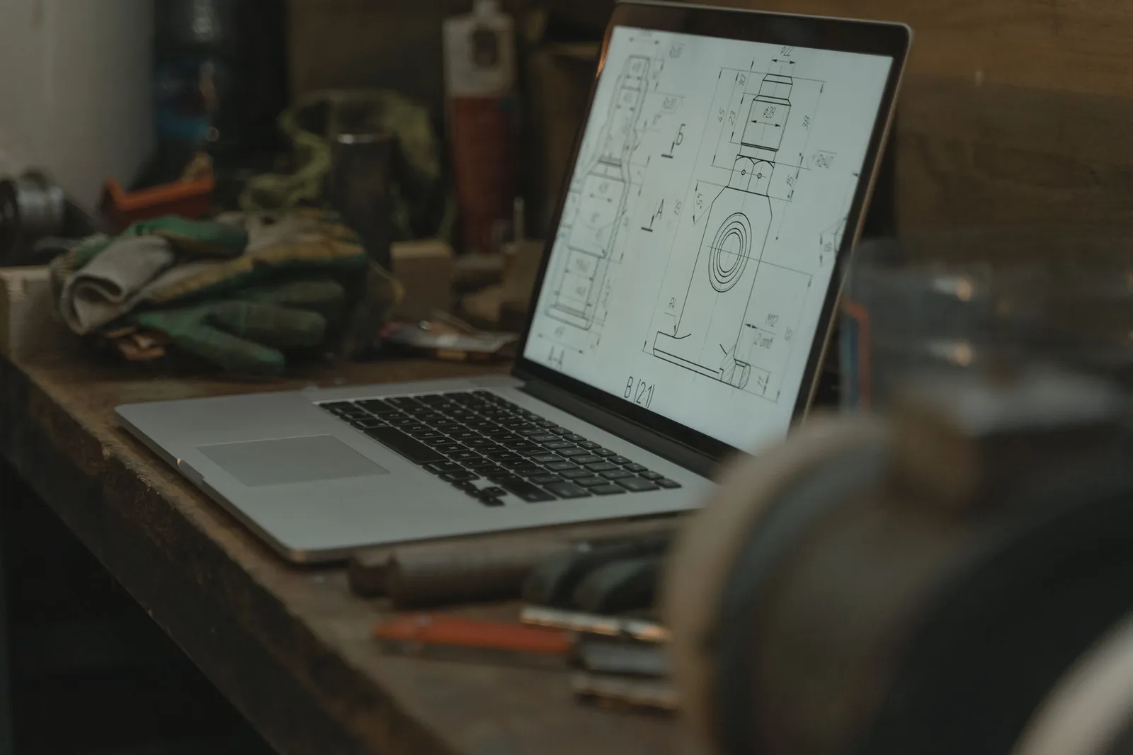
A one-off prototype brings the model to life before a hundred units are launched. It is used to check fit, assembly, ergonomics and actual compliance. Fixing a file costs a few hours; fixing a production run that has already been cut costs thousands of dollars.
The prototype reveals details no screen shows: a flange that gets in the way of a hand, screw access that is too tight, a weld that is hard to reach. These adjustments feed into the final version of the drawing.
For custom metal prototypes, producing the sample in the same shop as the future production run ensures that test results reflect production conditions. A prototype made elsewhere, on different machines, is only half reassuring.
Deliverables expected from both sides
A clean project relies on clear deliverables exchanged in both directions. The client provides the input data and approves; the engineering office delivers the files and drawings. The STEP exchange format (ISO 10303), published as an international standard, is designed precisely to transfer 3D geometry between different systems without loss of information.
| Deliverable | Formats | Purpose |
|---|---|---|
| 3D model | STEP, IGES, native SolidWorks | Reference geometry and simulations |
| Drawing set | DWG, DXF, PDF | Dimensions, tolerances and shop notes |
| Prototype | Physical part | Fit and function validation |
| Approved shop drawing | Signed PDF | Official authorization to fabricate |
The approved shop drawing is the pivotal document: it is what triggers production. It specifies alloys, finishes, welds and inspections. To see where this step fits in the whole process, read about the steps of a metal fabrication project and the options for custom parts fabrication.
Conclusion
Succeeding at 3D modeling of metal parts means cleanly connecting the initial idea to the approved shop drawing, by way of redrawing, feasibility validation, optimization and prototyping. Each step reduces uncertainty and protects the budget before the first cut.
A concept deserves to be designed by a team that models and fabricates under one roof, with the right formats and traceable documentation. To turn your idea into a production-ready drawing, explore the 3D planning service dedicated to metal parts and start your project on the right foot.
FAQ
What is 3D modeling of metal parts?
3D modeling of metal parts is the step that translates an idea, a sketch or an incomplete drawing into an exact three-dimensional digital model. This model is used to check feasibility, adjust tolerances and produce shop drawings. It becomes the shared reference between the client and the shop, which reduces errors, costly rework and delays before the parts are actually fabricated.
Which file formats should be provided for a 3D project?
A concept can start from a simple sketch, a photo or a partial drawing. For production, the most useful formats are STEP or IGES for 3D geometry, DWG or DXF for drawings and PDF for visual review. The native SolidWorks file remains ideal, but a good engineering office can convert and rebuild from partial data.
Is a prototype needed before launching production?
A one-off prototype is strongly recommended whenever a part is complex, critical or intended for series production. It confirms dimensions, fit and real manufacturability before material and shop hours are committed. Fixing a digital model costs little; fixing a hundred parts that have already been cut is expensive. The prototype therefore acts as an insurance policy that protects the schedule and budget of the entire project before production even starts.
How long does the 3D design stage take?
The timeline depends on the complexity, the number of parts and the quality of the input data. A simple component can be modeled and drawn in a few days, while a complete assembly requires more iterations. Providing reliable measurements, clear constraints and an available technical contact speeds up the process considerably. Working with an integrated shop reduces back-and-forth and shortens the path to an approved drawing.