Getting custom welded metal assemblies right depends on three levers: a planned welding sequence, rigid clamping on a fixture and controlled heat input. These measures limit shrinkage and buckling, and a final dimensional inspection then confirms the tolerances before the large assembly is delivered.
Fabricating a large assembly is not just about the moment of welding. It is decided well before, in how custom welded metal assemblies are clamped, sequenced and measured. A poorly planned weld bead can pull a part out by several millimeters and compromise the entire fit-up.
A shop's certification and compliance set the framework. Execution on the shop floor determines the final result. This article focuses on that hands-on work, from the welding fixture to dimensional inspection, for assemblies that fit together on the first try at the job site.
Why large welded assemblies distort
Welding is a thermal process before it is a joining process. The heated zone expands, then contracts as it cools. Because the surrounding metal stays cold and rigid, this contraction creates internal stresses that deform the material. These movements are not defects but physical consequences of the process.
The four main types of distortion
Distortion is generally classified as transverse shrinkage, longitudinal shrinkage, angular distortion and buckling. The Welding Institute describes these types and their causes in its knowledge base. Each one calls for a different response when the work is planned.
| Type of distortion | What happens | Preventive measure |
|---|---|---|
| Transverse shrinkage | The weld contracts across its width | Closely spaced tacks, clamping |
| Longitudinal shrinkage | Contraction along the length of the joint | Alternating sequence, short beads |
| Angular distortion | Uneven heating between the face and the root side | Pre-setting, balanced welding |
| Buckling of thin sheet | Compressive stresses | Temporary stiffeners, fixture |
The role of heat input
The higher the heat input, the more the affected zone expands and contracts. Limiting amperage, splitting the work into more passes and respecting the interpass temperature all reduce movement. On stainless steel, this control also protects corrosion resistance, a topic covered in the article on CWB certification for TIG welding.
Fixtures and welding sequence for custom welded metal assemblies
Distortion is prevented mainly through method, not correction. Two tools dominate: rigid clamping and the order in which beads are laid down. Combined properly, they keep the assembly within its dimensions without forcing mechanical rework.
Clamping and the welding fixture
A welding fixture locks the part's geometry before the first spark. It holds angles, center distances and squareness throughout the heating and cooling cycle. For production runs or large repeat assemblies, the fixture ensures that every unit comes out identical to the previous one.
Fixture assembly relies on precisely cut and formed parts. A clean fit-up upstream, achieved through CNC bending and cutting, reduces the gaps to fill and therefore the heat input required. Less heat means less movement.
Welding sequence and direction
The order of passes spreads heat out instead of concentrating it. Backstep welding, with beads alternating from one side to the other, and balanced welding around the neutral axis both even out the stresses. These distortion control techniques for welding are documented and proven on the shop floor.
A few simple principles guide sequence planning:
- Weld from the center toward the ends so shrinkage can escape.
- Alternate sides of a joint to balance angular distortion.
- Break long welds into short segments laid down in a backstep pattern.
- Tack solidly before welding continuously.
Planning a large welded assembly with tight tolerances? Have your welding sequence and clamping plan reviewed by a team of certified welders before production starts.
Tolerances and dimensional control of welded assemblies
A realistic tolerance is one the process can hold repeatably. Specifying too tight on a welded structure is expensive in rework; specifying too loose compromises the fit-up. The right setting comes from dialogue between the designer and the shop.
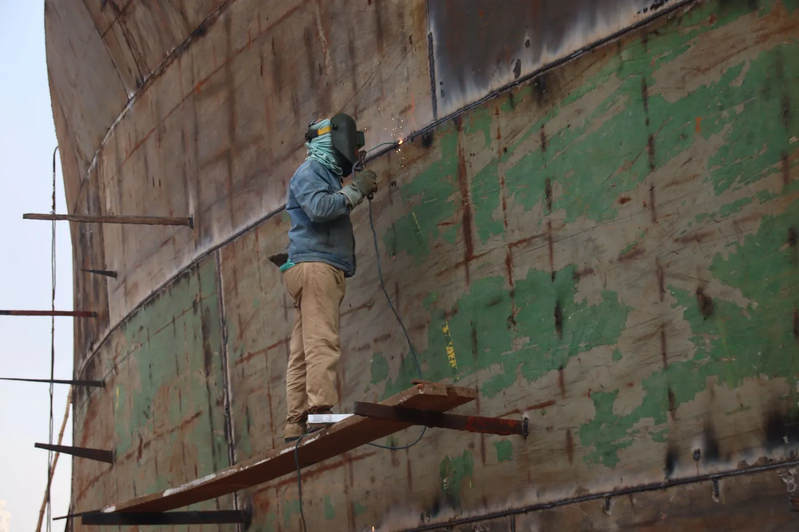
Tolerance standards
Tolerances for a welded assembly are wider than for machining because the process induces shrinkage. ISO 13920, the standard for general tolerances in welded construction, defines four classes selected according to functional requirements. For steel construction, the CSA W59 standard for welded steel construction governs workmanship quality.
In practice, critical dimensions and their class appear directly on the drawing. Machining operations performed after welding, such as bores or faced seats, fall under a separate standard. This combination avoids imposing machine-shop precision on an entire weldment.
Final dimensional inspection
Before shipping, the assembly is measured and compared against the drawings. Inspectors check squareness, flatness, the alignment of bolted interfaces and fastener center distances. A visual inspection of the welds, supplemented by non-destructive testing when required, confirms the soundness of the joints. Results are recorded in a traceable report, a natural reflex within an integrated manufacturing shop.
Fabricating in sections for transport and lifting
A large assembly is also designed around how it will leave the shop. Road transport, lifting capacity and handling often require splitting the work into sections that are then assembled at the job site. These interfaces are planned at the drawing stage.
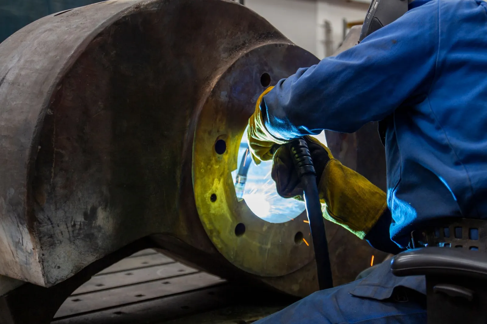
Splitting the work into modules brings several practical benefits:
- Staying within road load limits without a special permit.
- Turning parts over to weld in the flat position, which improves weld quality.
- Handling weights compatible with the available lifting capacity.
Lifting capacity sets the maximum size of a section. A 10-ton overhead crane, 24 feet of clear height and sufficient shop span determine what can be assembled, turned over and moved safely. The same constraints apply to large stainless steel structures, where each module must connect to the next without forcing. When planned well, section interfaces land within tolerance at the first bolt-up, with no adjustment on site. The steps of a fabrication project explain how these milestones fit together.
Conclusion
Reliable custom welded metal assemblies do not depend on luck but on method: anticipating distortion, clamping on a fixture, sequencing the welds, setting realistic tolerances and validating with a dimensional inspection. All of it is thought through upstream, with sections sized for transport and lifting. For a demanding project, plan the sequence, clamping and inspection early: request a technical review of your drawings before fabrication begins.
FAQ
What is a custom welded metal assembly?
Custom welded metal assemblies are fabricated to a client's precise drawings rather than built from standard components. They combine cutting, bending, fit-up and welding of stainless steel, aluminum or carbon steel parts. Each joint is designed to meet defined tolerances and limit thermal distortion, ensuring a final assembly that meets the project's functional requirements.
How can distortion be limited when welding a large assembly?
Controlling distortion combines several complementary techniques. Rigid clamping on a fixture holds the parts in position while they cool. A balanced sequence, such as backstep or alternating welding, spreads heat instead of concentrating it. Controlled preheating, limited heat input and strategic tacking also reduce shrinkage. Finally, pre-setting or pre-bending anticipates the metal's predictable movement.
Which tolerances apply to a welded assembly?
Tolerances for a welded assembly are wider than for machining because the process causes shrinkage as the metal cools. ISO 13920 offers four classes, from the tightest to the most common, chosen according to functional requirements. Critical dimensions are shown directly on the drawing, while post-weld machining falls under a separate standard. A final dimensional inspection confirms that the assembly meets the specified class.
Why fabricate a large assembly in sections?
Fabricating in sections addresses transport, lifting and handling constraints. An assembly too large for a standard road load is divided into modules and then assembled at the job site. This approach also makes it easier to turn parts over and weld in the flat position, which improves weld quality. Lifting capacity, such as that of a 10-ton overhead crane, determines the maximum size of the sections that can be handled.
Which inspection validates a welded assembly before delivery?
Before delivery, the assembly undergoes a dimensional inspection that compares actual dimensions with those on the drawings. The welders check squareness, flatness and the alignment of bolted interfaces. A visual inspection of the welds, supplemented by non-destructive testing when required, confirms the soundness of the joints. Results are recorded in a traceable report. This step confirms that tolerances are met and that the sections will connect correctly during final assembly.